
Introduction
Many refining processes require hydrogen, especially for desulfurization, hydrotreating, and hydrocracking. Some of the hydrogen is supplied as a byproduct of the catalytic reforming process, but that seldom is sufficient. The shortfall is typically supplied by a Hydrogen Plant.
The purpose of this document is to describe the Hydrogen Plant process and the process controls recommended for best efficiency.
Steam-Methane Reforming
The Hydrogen Plant produces hydrogen via the steam-methane reforming reaction:
CH4 + H2O à 3H2 + CO (1)
Natural gas (feed gas) is combined with superheated steam (process steam) and charged to the Hydrogen Plant reformer furnace. The process steam and feed gas mixture passes through catalyst-filled tubes in the radiant section. The reaction is highly endothermic, so the reaction takes place inside the tubes of a furnace to provide the necessary heat.
The reaction equation shows that a minimum of one mole of steam is required per mole of methane. To minimize coking in the furnace tubes, an excess of steam is required, usually in the range of 2.0 to 2.5 moles steam per mole methane. Any steam above the minimum ratio consumes energy without providing benefits. Therefore, precise control over the steam-to-methane ratio is important to energy efficiency and to unit run length.
Hydrogen Purification
The effluent from the reforming furnace contains CO along with the hydrogen product. The CO must be removed because it will poison the catalyst in the downstream reactors. The CO is converted to CO2 via the water-gas shift reaction:
CO + H2O à CO2 + H2 (2)
The CO2 is then absorbed by a solvent, such as MEA. The rich solvent is stripped of its CO2 and returned to the absorber.
Any CO or CO2 remaining in the hydrogen product stream is converted to CH4 via the methanation reaction:
CO + 3H2 à CH4 + H2O (3)
CO2 + 4H2 à CH4 + 2H2O (4)
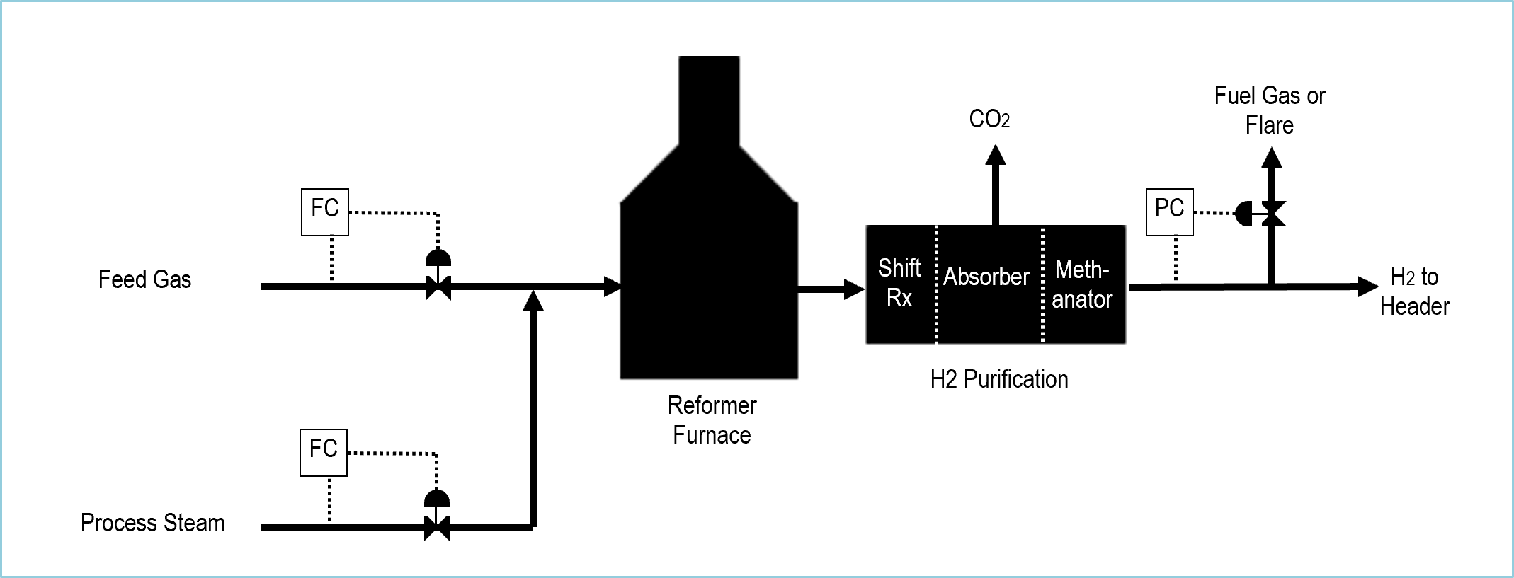
Figure 1 is a simplified process flow diagram of a typical Hydrogen Plant. Feed gas is combined with superheated process steam and sent to the reformer furnace. As mentioned previously, the mixture flows through catalyst in the furnace tubes wherein the steam-methane reforming reaction takes place.
The reactor effluent then goes to the purification section. The shift reactors perform the water-gas shift reaction to convert CO to CO2. Most of the CO2 is then absorbed in the absorber and expelled in the stripper. Finally, any remaining CO and CO2 in the hydrogen product stream is converted to CH4 in the methanator.
Excess hydrogen is sent to the fuel gas system and/or the flare on pressure control.
Steam to Carbon Ratio Control
The Steam-to-Carbon Ratio Control application adjusts the process steam rate to maintain the desired steam-to-carbon ratio setpoint. The feed gas normally contains more hydrocarbons than just methane. Those heavier hydrocarbons can also be reformed into hydrogen similarly:
C2H6 + 2H2O à 5H2 + 2CO (5)
C3H8 + 3H2O à 7H2 + 3CO (6)
C4H10 + 4H2O à 9H2 + 4CO (7)
C5H12 + 5H2O à 11H2 + 5CO (8)
C6H14 + 6H2O à 13H2 + 6CO (9)
Note that the moles of steam required are the same as the number of carbon atoms in the hydrocarbon. Therefore, steam-to-carbon ratio is used as the control variable rather than steam-to-methane ratio when natural gas is used as a feed instead of pure methane.
The Steam-to-Carbon Ratio Control application includes cross-limiting control that forces the process steam to lead the feed gas on an increase and lag the feed gas on a decrease. The application also includes a feed gas setpoint ramp that allows the operator to set a target feed gas rate. The target rate is gradually achieved while the steam rate is adjusted to maintain the steam-to-carbon ratio setpoint. Figure 2 shows how these features are implemented.
The signal selectors shown in Figure 2 perform the required logic. The low select (<) provides the setpoint to the feed gas flow controller. When the feed gas rate is increased, it prevents the feed gas rate from increasing before the process steam increases.
The high select (>) provides the feed gas rate to the carbon rate calculation, whose output goes to the ratio controller that adjusts the process steam. When the feed gas rate is decreased, the selector prevents the process steam from decreasing until the feed gas rate responds.
This feature ensures that whenever the feed gas rate is increased, the steam-to-carbon ratio never decreases Therefore, the ratio setpoint can be set near the absolute minimum without concern for venturing into insufficient steam territory.

Reformer Furnace Controls
Outlet Temperature Control
The reformer furnace outlet temperature is an important control variable in the Hydrogen Plant process. It determines how much feed gas is converted to hydrogen. If the temperature is set too low, unconverted feed gas components end up in the hydrogen product thus reducing its purity. If it is set too high, excessive coking will occur in the furnace tubes.
The temperature is typically controlled via a cascade control scheme The outlet temperature controller outputs to the fuel gas flow controller setpoint, as shown in Figure 3.
Feedforward Control
The reformer furnace outlet temperature has a considerable time lag in responding to fuel gas changes. Therefore, changes in feed gas rate and temperature and process steam rate and temperature will cause a deviation in the outlet temperature until it responds to the fuel gas.
To minimize these deviations, feedforward control is included to automatically adjust the fuel gas rate to offset the disturbance. Separate feedforward calculations are performed for feed gas and process steam to account for their different heat capacities and temperatures. The summer (+) combines the two calculated feedforward actions and sends the result to the feedforward input of the outlet temperature controller. Figure 3 illustrates the application.
For example, if the feed gas and steam rates increase, then the feedforward calculation determines the appropriate increase in fuel gas for each to prevent a drop in the furnace outlet temperature. The resulting fuel gas increase is added to the fuel gas rate required by the outlet temperature controller to maintain its setpoint. If the feedforward dynamics are tuned properly, the furnace outlet temperature will deviate very little from its setpoint.