
Application engineers sometimes encounter control loops having multiple control valves. A typical application incorporates two valves in parallel to:
- provide more precise flow control via a small valve while using a larger valve to keep the small valve in control range (often called “big valve – little valve”).
- maximize overall efficiency by minimizing the position of the least efficient control valve.
The purpose of this document is to explain why these control schemes are used and give examples of their use.
More Precise Flow Control
SRU Example
In some processes, precise control over a flow is essential to meeting the process objectives. A good example can be found in the Sulfur Recovery Unit (SRU), which is a commonly found refining process for converting H2S absorbed from fuel gas into elemental sulfur.
SRU Process Overview
The first step in the SRU process is to convert a portion of the H2S into SO2 in the External Combustion Chamber:
2H2S + 2O2 -> SO2 + 2H2O (1)
The combustion products flow into a thermal reactor and continue on to two or more catalytic reactors in which the H2S and SO2 react to form sulfur:
2H2S + SO2 <-> 3S + 2H2O (2)
The sulfur vapor is condensed out of the reactor effluent and sent to the sulfur pit. The remaining tail gas flows to a Tail Gas Cleanup unit for further H2S removal before being discharged to the atmosphere. Figure 1 shows a simplified process flow diagram.
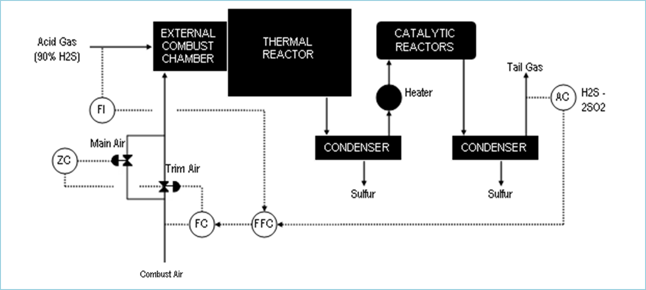
Figure 1: Sulfur Recovery Unit Process Flow
SRU Control Scheme
The primary control objective is to maintain a 2-to-1 molar ratio of H2S to SO2 in the reactors to conform to the stoichiometry of the reaction, thus maximizing sulfur recovery. However, the only location where the composition can be analyzed is the tail gas at the end of the unit. Therefore, an analyzer measures the tail gas H2S and SO2 content and the calculated excess moles of H2S (= H2S – 2SO2) becomes the input to an analyzer controller (AC). The AC is cascaded to an acid gas ratio controller (FFC), which is cascaded to a combustion air flow controller (FC). The FFC provides feedforward control for acid gas rate changes, which occur all too often in a typical refinery.
Precise control over the combustion air flow is extremely important in this process because of the sensitivity of the excess H2S calculation to combustion air flow. Therefore, the air flow is split into a main air line containing a control valve designed for full air flow and a trim air line containing a control valve designed for a small fraction of the total air flow. The trim air valve is adjusted by the combustion air FC and the main air valve by a valve position controller (ZC).
The ZC obtains the trim air valve position as its input and adjusts the main air valve to keep the trim air valve in control range. The ZC is typically a “gap” controller in which no control action occurs within the gap (e.g., 40-50% trim air valve position).
Feedforward Action
In this example, a flow controller is connected to the trim air valve. Flow is a very fast responding loop, so when the ZC adjusts the main air valve, the flow controller quickly offsets the flow disturbance via feedback. Therefore, the flow deviates very little from setpoint.
However, if the control loop is a slower responding variable, such as temperature or analyzer, then the ZC could cause a sizable deviation until the feedback eliminates the deviation. To minimize the deviation, the ZC control action should be fed-forward to the trim air valve position. The feedforward action would adjust the trim air in the opposite direction whenever the ZC moves the main air valve. The details of feedforward control are discussed in another SAS Functional Specification.
Maximize Overall Efficiency
Combustion Air Example
Sometimes two valves are needed to provide both fast control response and economical operation. A good example can be found in excess oxygen control of a forced-draft fired heater. The combustion air can be controlled either by adjusting a damper in the FD fan discharge, or via the governor which sets the fan speed (turbine or VFD).
Forced Draft Fired Heater Process Overview
The combustion air flow can be regulated by either the damper or the FD fan governor. The damper provides faster response to air flow, but closing off the damper puts extra load on the fan, which costs energy (either steam if a turbine or electricity if a motor).
Therefore, the two outputs should be coordinated to provide fast response at minimum energy cost. The best approach is to control with the damper mostly open and adjust the governor when the damper gets too far open or closed.
Figure 2 shows the process flow for a typical forced-draft fired heater.
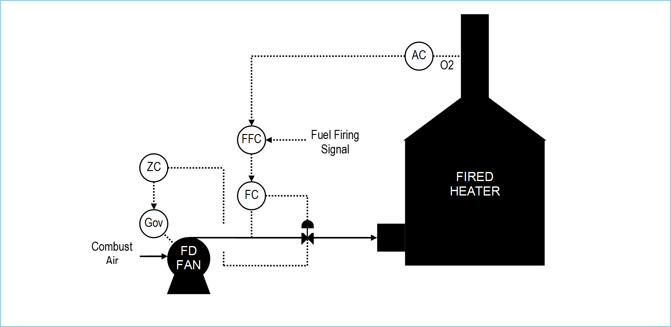
Figure 2: Forced Draft Fired Heater
Combustion Air Control Scheme
The primary control objective is to maintain the excess oxygen at the optimum setpoint, thus maximizing heater efficiency. An analyzer measures the flue gas O2 which becomes the input to an analyzer controller (AC). The AC is cascaded to an air-to-fuel ratio controller (FFC), which is cascaded to a combustion air flow controller (FC). The FFC provides feedforward control for changes in fuel firing rate.
The combustion air FC adjusts the damper, and a valve position controller (ZC) adjusts the governor. The ZC obtains the damper position as its input and adjusts the governor to keep the damper in control range but mostly open. The ZC is typically a “gap” controller in which no control action occurs within the gap (e.g., 75-85% damper position).
Please note that the ZC setpoint should be higher and the gap limits tighter (3-5%) compared to the previous case where more precise flow control was the objective.
Feedforward Action
In this example, a flow controller is connected to the damper. Flow is a very fast responding loop, so when the ZC adjusts the governor, the flow controller quickly offsets the flow disturbance via feedback. Therefore, the flow deviates very little from setpoint.
However, if the control loop is a slower responding variable, such as temperature or analyzer, then the ZC could cause a sizable deviation until the feedback eliminates the deviation. To minimize the deviation, the ZC control action should be fed-forward to the damper position. The feedforward action would adjust the damper in the opposite direction whenever the ZC moves the governor. The details of feedforward control are discussed in another SAS Functional Specification.